Wednesday, 27 January 2021

From PDF to a Useful Part

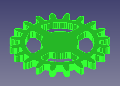
 The gear example in this post came from a pdf intended for scroll saw users. This type of pdf can be opened directly in Inkscape.  The idea is the parts are printed on paper at full scale and the paper is then glued to a piece of wood.


 It's also possible to extract a drawing from a generic pdf using Inkscape's import via poppler option.  This wrench was extracted from a pdf repair manual.  The commands Ungroup, Path Break Apart and Path Combine were used to complete the task.  This trick could come in handy for transforming a logo to dxf or getting artwork for engraving.

This post is in part an expansion of a previous post:

https://steppingintocnc.blogspot.com/2021/01/freecad-dxf-problem-and-solution.html  


The pdf page on the left has some items that need to be removed as gear on the top right is all that's needed.  A sharp eye will notice a cleaner drawing exists on the bottom left so this isn't the best example.  Also Acrobat Reader has tools to simplify this task but open source tools do all that's needed.


In Inkscape turn off the page border in drawing preferences.  Left click and drag a selection box around the desired item.  From the Edit menu select invert selection and hit the delete key.  The page is now reduced to the image on the left.


 The image on the left shows all that is needed from the pdf page.  Reaching  this point can be a bit of a pixel hunt but drag-select can speed things up considerably.


Inkscape can export in dxf format but I've had some less than great experiences with that exporter.  QCAD has a very good svg importer so the drawing was saved as an Inkscape svg.  Inkscape by default is set to 90 dpi but if unsure check the application preference settings.

On the left is the svg imported in QCAD.  There are a huge number of segments so a decision will need to be made whether use as-is or recreate some of the geometry.  In this case the mess of segments in the centre were replaced with a true circle.  Before saving the dxf file make sure the drawing preferences are set to mm.


The next step is importing the dxf into FreeCAD.  It's also possible to import the svg file directly into FreeCAD but I find it easier to manipulate this type of file in QCAD.  I also have some reason to suspect the QCAD dxf is a more accurate representation of the original drawing compared to how FreeCAD interprets the svg.

From this point on the procedure is a rehash of the post mentioned at the top of this page.  And now a small note regarding the pocketing operation problems that prompted that post..............


    On this part I had best results by making the pocket the first operation and some grief doing this in any other order.  The vertical surface of the pocket is easily selected as the pocket geometry.  Good thing I got rid of all the segments eh ?

Monday, 25 January 2021

Tool Length Offsets

 My newest toys for the cnc mill are Tormach tool holders.  Using these tool holders makes tool lengths repeatable unlike a standard R8 holder. Now tool changes are possible in the program instead of using 1 program per tool.  Linuxcnc with Axis UI is used but the interface shouldn't matter as the commands are in MDI.

X and Y offsets are fairly straight forward because they are based on the vertical centre of the spindle which does not change with tool length or diameter.  The Z offset changes every time a tool of different length is used.  The machine needs to adapt it's Z movements to accommodate tools of varying lengths and it does this using tool length offsets or TLO in short.


Tormach holders compress against the face of the spindle.  The distance from that contact point to the tip of the tool equals the total length of the tool.

tool + holder = TLO


I've chosen a method of TLO that results in all offsets being positive because they describe the true length of the tool.  My method is far from the only way and there are certainly more automated approaches.  It's old school and a variation on how tool are measured offline with a setting fixture and height gauge. The link below provides a good explanation of the pros and cons of positive TLO:

https://www.cnccookbook.com/touch-off-tool-setter-measuring-tools-for-length/

as the man says positive offsets demand caution.


 The image to the left shows the spindle face touching a block that is reserved for this purpose.  This is the position where G54 is set to zero.

btw the machine isn't out of tram,  the photographer has no skills. 


--> In MDI enter T0 M6 and also a G49 for an added bit of safety.

--> Lower the spindle face until it touches the top of the measuring block.

--> Set the current position to G54 Z0 using a touch-off button in the UI or entering G10 L20 P1 Z0 in MDI.

--> Set the DRO to read relative position.  It should now be reading Z0.

--> Place T01 in the spindle and move the tool tip to the top of the setting block.  The DRO will now display the distance from the tool tip to the spindle face. The DRO is being used as a poor man's height gauge.

--> Enter the displayed DRO Z value directly in the tool table (not recommended) or in MDI enter T01 M6 and G10 L10 P1 Z0

-->Place T02 in in the spindle and move the tool tip to the top of the setting block.

-->In MDI enter T02 M6 and G10 L10 P2 Z0.  Notice that P represents the tool #

Continue that pattern for any additional tools. MDI displays a command history so the commands don't need to be memorized.  Below is a small test program for 3 tools:

#######################################

(move block somewhere other than directly under tool)
g90
g20
g54
g53 g0 z0
(if G53 crashes it's time to rethink the machine's basic setup)
T1 M6
G54
g0 x0 y0
g43 z2 h01
g01 z.1 f50
z0 f20
m0
(slide block under tool to check)
(remove block and resume program)
g01 z0.1
g53 g0 z0
t2 m6
g49
g00 x0 y0
g43 z2 h02
g01 z.1 f50
z0 f20
m0
(slide tool under tool to check)
(remove block and resume program)
g01 z.1
G53 g0 Z0
t3 m6
g49
g00 x0 y0
g43 z2 h03
g01 z.1 f50
z0 f20
m0
(slide block under tool to check)
(remove block and resume program)
g01 z0.1
g53 g0 z0
m2

###############################

If all has gone to plan running this program should result in each tool travelling to the top of the setting block, no more and no less.  So why use positive TLO instead of the more common method used in the hobby world ?  Place a different height of block on the table.  Now load any of the already measured tools in the spindle taking care that the correct TLO is active.  Move the tool tip to the top of the new surface and set G54 to Z0.  If the test program is run again all tools should stop at this new Z height.  Cool trick but I don't recommend setting G54 this way.  Instead set G54 using the spindle face.

--> in MDI enter T0 M6 and G49

--> Now move the spindle face to the top of the new block (or work piece).  Now set G54 to Z0 and rerun the test program (or another program).  The TLO when set as outlined above are portable to any work piece, only fixture offsets need to be changed.

If tools start crashing I'll return to edit this post but no crash is expected due to the methods.  However human error is expected and in my case guaranteed.

An above average youtube video that relates to this topic:


Wednesday, 20 January 2021

FreeCAD: A DXF Problem and a Solution

 DXF isn't FreeCAD's native format but sometimes it's the file format you're given.  I'm starting a new clock build and dxf is what the designer supplied.

QCAD is diplaying a huge number of segments.  The first temptation is to completely reconstruct the drawing into something sensible but maybe FreeCAD can deal with it as-is ?


The dxf is imported into FreeCAD's Draft Workbench.

Edit -> Select All

Modification -> Draft to Sketch

When transformation to sketch is complete hit delete on the keyboard to get rid of all the imported shapes.


In the Sketcher Workbench:

Sketch -> Validate Sketch

Use the resulting dialogue box to examine the sketch for errors.  In this case 1244 missing coincidences were found.  Click fix to repair.  No other errors were found.


In Part Design Workbench select Create a Body from the toolbar.  Right click the sketch in tree view and select move object to other body.  Pad the sketch to desired thickness.


In Path Workbench create job object as usual.  Now comes the part that wasn't working for me until a user  posted a solution in the FreeCAD forums.

https://forum.freecadweb.org/viewtopic.php?f=15&t=54540
 

Do not try a pocket operation on this part.  Choose a profile operation and select the bottom face as the  base geometry.  In the operation options select: Outside,  Holes,  Circles, Perimeter,  Compensation.


 Another possibility is adding a bottom surface and choosing that surface for pocketing.  The downside is a longer calculation time and really there's nothing gained from grinding up the excess material


FreeCAD also has a Legacy dxf importer that apparently works better in some cases.  There's also many settings available in Preferences.  My options are all set to whatever defaults come with the FreeCAD.  Units can be a source of confusion with dxf files and I find good 2D CAD software is the best place to deal with such things and anything dxf really.  My longtime go-to is QCAD.  


Tuesday, 19 January 2021

Arc-fitting and Arc-breaking with bCNC

 How does CAM deal with constant radius arcs and near-arcs ?  Fusion 360 has smoothing and tolerance settings in the general operation (pre-post process) dialogue box which determines how splines are treated in terms of tangent arcs or line segments. The actual post process may make additional changes.  It will attempt to do arc-fitting if told to do so.  FreeCAD doesn't have an exact equivalent to the best of my knowledge.  It does have a user settable geometry tolerance setting but I haven't found any documentation that describes what this does in any detail.  It does do some arc-fitting as will be described further down this page.  True arcs are output as G2/G3 in both Fusion and FreeCAD although Fusion 360 includes at least one post process that posts all arcs as line segments.

This topic was prompted by a couple of things.  First was an earlier post about nesting and discovering Deepnest can do bad things to arcs.  Second was seeing the elimination of G2/G3 as a recurring topic on the FreeCAD forums.

Among the many interesting things bCNC can do with existing g-code are the tools Linearize and ArcFit.  Arc fitting will attempt to replace a series of line segments that approximate an arc with G2/G3 arcs.  Linearize does the opposite, replacing G2/G3 arcs with line segments.

The image to the left is the QCAD property editor looking at a dxf exported from Deepnest.  A 50mm circle has a circumference of 157mm and with a 0.050mm curve tolerance set in Deepnest there are only 144 segments ? Curve Tolerance doesn't work exactly as I expected.  No problem as this dxf resulted in FreeCAD posting G2/G3 arcs.  It appears FreeCAD does arc-fitting even if the setting is not visible to the user.

Click on any image to enlarge


In another case Deepnest has broken a 38.1mm circle into 40 segments.  FreeCAD's g-code output has refined the arc by increasing the number of segments to 74.  No G2/G3 arcs were produced.  The tool used was 6.35 diameter.

Using the settings seen on the left bCNC replaced the 74 line segments with 6 arcs.  The maximum deviation from the true diameter was 0.03mm compared to the 0.17mm deviation found in the original FreeCAD output.  Setting a finer arc precision in bCNC creates more arcs and may reduce deviation even more.  My testing didn't explore this further.


  The image on the left is the bCNC editor displaying the results of arc fitting.  This 12 line block will replace the 77 line block created by FreeCad.  The 77 line block is listed directly above the expanded 12 line block.


Below is the exported file from bCNC is 21 lines replacing the original 105 line FreeCAD file.  Somehow the 5mm Z cut depth was lost,  possibly due to user error.

G17 G54 G40 G49 G80 G90
G21
G54
M5
M6 T1
G43 H1
M3 S0
G0 Z5.000
G0 Z3
G0 X15.705 Y15.705
G0 Z0
G2 X20.584 Y8.357 I-15.222568 J-15.40144 Z0 F400
G2 X21.695 Y-4.781 I-21.577207 J-8.440627 Z0
G2 X-1.383 Y-22.197 I-21.894967 J5.014727 Z0
G2 X-22.197 Y1.382 I1.67678 J22.456271 Z0
G2 X8.931 Y20.344 I22.263697 J-1.517216 Z0
G2 X15.705 Y15.705 I-8.605303 J-19.831003 Z0
G0 Z3
M05
G17 G54 G90 G80 G40
M2


On the left is FreeCAD g-code displayed in the bCNC editor.  The next block in the editor is the output of Linearize which broke the G2/G3 arcs into many straight segments.  Notice the block of linearized g-code is 1045 lines.  Click to enlarge the image.


   The image on the left shows the settings that created the large number of straight segments.


Linearize could be useful foe Easel users or others unable to use G2/G3 in the g-code.  ArcFit could be more universally useful.  For example g-code created using  files made in Inkscape from photo or pdf  are possible candidates.


Thursday, 7 January 2021

Letting CAM do the Math

 The tool path here is more complex than the chevron in the previous post.  With curves and tangent points and having to translate those curves and points to rotary positions CAM makes a lot of sense.

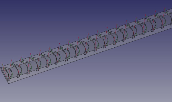
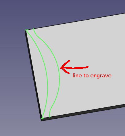
This starts with a bit of a workaround of a current FreeCAD limitation.  Neither Slot nor Profiling an edge work with curves at the time of this posting.  The geometry here is created to use an Engrave tool path.  Instead of drawing the true intended geometry,  a single edge of the slot is drawn at an offset equal to the tool radius.  This offset edge is cut with an Engrave operation which follows the edge as a tool centre-line tool path.  This trick can be handy in other situations as well.

Getting the job oriented can be confusing.  The easiest way I found was orienting the sketch vertically in the (x-, y+) quadrant . With this orientation the A rotation moves are positive and X0 is the part face furthest from the chuck.  Tool path cutting moves will begin at the point furthest from the chuck.  This assumes the common set-up of machine X+ moves advancing the tool towards the face of the chuck.  This may look wrong but it posts correctly.


In the LinearPattern dialogue the full length of the part was entered and the number of feature repeats.  Unexpectedly to get 23 pockets the entry box needs an input of 24 ?


The resulting linear pattern. 


The curves to select for the Engrave operation.  The other lines were needed to make a closed shape so the sketch could be pocketed in CAD.  All 23 of the curved paths were selected.  Lead-ins/outs were applied.  Path has an array tool that I haven't tested.


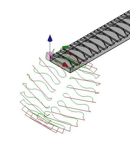
Wrapping the Y axis around the A axis.

The cylinder is 89mm in diameter.


After the axis wrap is applied the tool path looks like this.  The post processor included no Y on the initial approach so it was added in a text editor.


A back plot of a similar part in linuxcnc. It shows Z moves from the inside out  so something is a bit off in my display settings.  It does run correctly. 


Tuesday, 5 January 2021

Is CAM the Answer ? It Depends on the Question.

My first encounters with g-code were in a shop with no CAM software.  This may sound strange to those who only know a time with easy access to CAM software but I pre-date the internet and powerful personal computers.  In fact the huge files that CAM software can post would have been a nuisance given the limited storage available on old equipment.  Also some machines stored programs on magnetic or paper tape but that's a war story for another day.  Cutter compensation (G41/G42), Macros and sub-programs  have fallen out of common use but we needed these daily.  These days cutter compensation is more likely to be used as wear offsets rather than used to compensate full radius or diameter.

What brought this to mind was a small job involving cutting a repeating chevron pattern around the circumference of a pipe.  FreeCAD has an axis-wrap Path dress-up which will be the topic of the next post.  In this case FreeCAD came close but just wouldn't bend to my will entirely.

The tool path itself is very simple, it's just a matter of repeating it at regular intervals of rotation.  A Macro or sub-program can do this and although linuxcnc doesn't have exactly those things it has the o-word which is a substitute:   http://www.linuxcnc.org/docs/html/gcode/o-code.html

O-word programs have the downside of being miserable to start anywhere but the top of the program.  Also any edit inside a loop affects all iterations of that loop.  There is a way to get CAM-like output that is fully customizable using a real programming language like Python.  I'm not a programmer so my code is clumsy but all that's needed is a loop and variables. I didn't bother figuring out how to get blogger to do fancy syntax highlighting so here it is raw:

*************************************************************                                      

#!/usr/bin/env python3
import math
## this script is run from terminal by typing
## python3 <name of this py script>  >  <name of output file>
## i is the rotated approach position
## n is counting the number of loops
## end ="" prevents printing new line in python3
## round function to limit oupput to 4 decimals
i = 0
n = 1
print("(0.25 EM)")
print("(# 3.5 inch tire)")
print("G54")
while (i < 347):
    print("G00 X-0.3 Y0 A", end ="")
    print(round(i, 4))
    print("G01 Z-0.1 F50")
    print("X0 F30")
    print("G01 X0.72 A", end ="")
    print(round(i + 13.61, 4))
    print("G01 X1.44 A", end ="")
    print(round(i, 4))
    print("G01 X 1.64")
    print("G00 Z 0.2")
    print("(", end ="")
    print(n, end ="")
    print(")")
    i = i + 15.7154
    n = n + 1
print("M02")
exit()

******************************************

and the first few lines of the output:

 (0.25 EM)
(# 3.5 inch tire)
G54
G00 X-0.3 Y0 A0
G01 Z-0.1 F50
X0 F30
G01 X0.72 A13.61
G01 X1.44 A0
G01 X 1.64
G00 Z 0.2
(1)
G00 X-0.3 Y0 A15.7154
G01 Z-0.1 F50
X0 F30
G01 X0.72 A29.3254
G01 X1.44 A15.7154
G01 X 1.64
G00 Z 0.2
(2)

It includes a handy loop counter.  I'm not about to become a proficient python coder but simple routines like this are easy and useful.  Another thing added to the toolbox.


Sunday, 3 January 2021

Deepnest is Open Source Nesting Software

This starts with a sketch in FreeCad. Six simple shapes and a rectangle large enough to contain the shapes.  The container shape does not need to be a rectangle,  it could be an odd shape piece of material.  Export the sketch as dxf.  The shapes can not be inside another shape.  For example the rectangle on the right is empty.


The configuration settings in Deepnest.  I changed the Curve tolerance to 0.002".  Unfortunately Deepnest  tolerance doesn't work exactly as expected and that will be the topic of an upcoming post on arc-fitting.  Freecad exported the  sketch dxf in mm so that's chosen here as the import units.  The export setting is inches.  The Space between parts is set to 0.25" to match the diameter of the cutter.  There are mouse-over tool tips to explain the settings.

A true 2D drawing program like QCAD would probably be a better choice to create the dxf file.  Deepnest can also work with svg files.


Here the 4.4" x 3.6" rectangle has been chosen as the container.  Note the option to create multiples of the shapes.  All or none of the shapes can be selected and Deepnest will fit as many as possible.  At the bottom left (not shown) there is a small square icon that will create a container rectangle if none is included in the sketch.


This was the first and best nest.  Deepnest will continue trying new arrangements until the stop button is clicked.


This was the best of the alternatives offered.  Clicking on the colour bars on the left will display the various nests offered.


All that's left to do is exporting the dxf.  I find that FreeCad will not open this dxf correctly unless it is first opened and saved in QCAD.

In FreeCad import the dxf into Draft Workbench.  Choose "select all" from the edit menu.  Perform a Modification -->  Draft to Sketch.  Take the opportunity to hit the delete key to delete the associated shape entries while they are still highlighted in the tree.

In the Part Workbench select the sketch and extrude.  Create a cube to act as a base for the extrusion.  Then select everything and make a compound.


In the Path Workbench choose the compound as the model.  The tool is a 1/4" end mill.  The image on the right is the cut simulation and it looks okay.  The dxf from Deepnest returned all the original measurements for these simple parts.  The circle has become a series of line segments as you might expect from a dxf.  If the segments are short enough FreeCAD can output g-code containing G2/G3 arcs.  If the segments are too long the g-code output will be a circle approximation using line segments.  This is discussed further in a post labelled 'Arc-fitting and Arc-breaking with bCNC'