Thursday, 7 January 2021

Letting CAM do the Math

 The tool path here is more complex than the chevron in the previous post.  With curves and tangent points and having to translate those curves and points to rotary positions CAM makes a lot of sense.

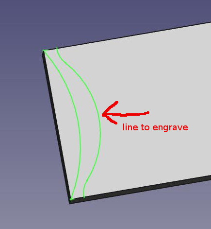
This starts with a bit of a workaround of a current FreeCAD limitation.  Neither Slot nor Profiling an edge work with curves at the time of this posting.  The geometry here is created to use an Engrave tool path.  Instead of drawing the true intended geometry,  a single edge of the slot is drawn at an offset equal to the tool radius.  This offset edge is cut with an Engrave operation which follows the edge as a tool centre-line tool path.  This trick can be handy in other situations as well.

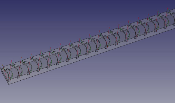
Getting the job oriented can be confusing.  The easiest way I found was orienting the sketch vertically in the (x-, y+) quadrant . With this orientation the A rotation moves are positive and X0 is the part face furthest from the chuck.  Tool path cutting moves will begin at the point furthest from the chuck.  This assumes the common set-up of machine X+ moves advancing the tool towards the face of the chuck.  This may look wrong but it posts correctly.


In the LinearPattern dialogue the full length of the part was entered and the number of feature repeats.  Unexpectedly to get 23 pockets the entry box needs an input of 24 ?


The resulting linear pattern. 


The curves to select for the Engrave operation.  The other lines were needed to make a closed shape so the sketch could be pocketed in CAD.  All 23 of the curved paths were selected.  Lead-ins/outs were applied.  Path has an array tool that I haven't tested.


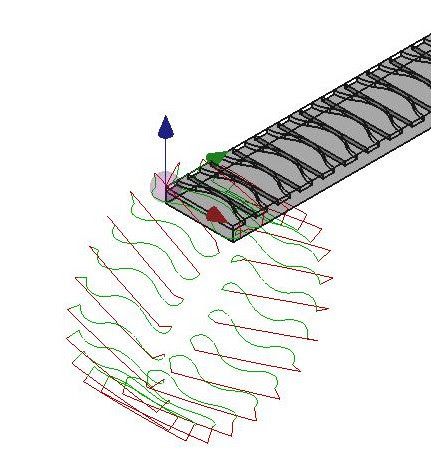
Wrapping the Y axis around the A axis.

The cylinder is 89mm in diameter.


After the axis wrap is applied the tool path looks like this.  The post processor included no Y on the initial approach so it was added in a text editor.


A back plot of a similar part in linuxcnc. It shows Z moves from the inside out  so something is a bit off in my display settings.  It does run correctly. 


Tuesday, 5 January 2021

Is CAM the Answer ? It Depends on the Question.

My first encounters with g-code were in a shop with no CAM software.  This may sound strange to those who only know a time with easy access to CAM software but I pre-date the internet and powerful personal computers.  In fact the huge files that CAM software can post would have been a nuisance given the limited storage available on old equipment.  Also some machines stored programs on magnetic or paper tape but that's a war story for another day.  Cutter compensation (G41/G42), Macros and sub-programs  have fallen out of common use but we needed these daily.  These days cutter compensation is more likely to be used as wear offsets rather than used to compensate full radius or diameter.

What brought this to mind was a small job involving cutting a repeating chevron pattern around the circumference of a pipe.  FreeCAD has an axis-wrap Path dress-up which will be the topic of the next post.  In this case FreeCAD came close but just wouldn't bend to my will entirely.

The tool path itself is very simple, it's just a matter of repeating it at regular intervals of rotation.  A Macro or sub-program can do this and although linuxcnc doesn't have exactly those things it has the o-word which is a substitute:   http://www.linuxcnc.org/docs/html/gcode/o-code.html

O-word programs have the downside of being miserable to start anywhere but the top of the program.  Also any edit inside a loop affects all iterations of that loop.  There is a way to get CAM-like output that is fully customizable using a real programming language like Python.  I'm not a programmer so my code is clumsy but all that's needed is a loop and variables. I didn't bother figuring out how to get blogger to do fancy syntax highlighting so here it is raw:

*************************************************************                                      

#!/usr/bin/env python3
import math
## this script is run from terminal by typing
## python3 <name of this py script>  >  <name of output file>
## i is the rotated approach position
## n is counting the number of loops
## end ="" prevents printing new line in python3
## round function to limit oupput to 4 decimals
i = 0
n = 1
print("(0.25 EM)")
print("(# 3.5 inch tire)")
print("G54")
while (i < 347):
    print("G00 X-0.3 Y0 A", end ="")
    print(round(i, 4))
    print("G01 Z-0.1 F50")
    print("X0 F30")
    print("G01 X0.72 A", end ="")
    print(round(i + 13.61, 4))
    print("G01 X1.44 A", end ="")
    print(round(i, 4))
    print("G01 X 1.64")
    print("G00 Z 0.2")
    print("(", end ="")
    print(n, end ="")
    print(")")
    i = i + 15.7154
    n = n + 1
print("M02")
exit()

******************************************

and the first few lines of the output:

 (0.25 EM)
(# 3.5 inch tire)
G54
G00 X-0.3 Y0 A0
G01 Z-0.1 F50
X0 F30
G01 X0.72 A13.61
G01 X1.44 A0
G01 X 1.64
G00 Z 0.2
(1)
G00 X-0.3 Y0 A15.7154
G01 Z-0.1 F50
X0 F30
G01 X0.72 A29.3254
G01 X1.44 A15.7154
G01 X 1.64
G00 Z 0.2
(2)

It includes a handy loop counter.  I'm not about to become a proficient python coder but simple routines like this are easy and useful.  Another thing added to the toolbox.


Sunday, 3 January 2021

Deepnest is Open Source Nesting Software

This starts with a sketch in FreeCad. Six simple shapes and a rectangle large enough to contain the shapes.  The container shape does not need to be a rectangle,  it could be an odd shape piece of material.  Export the sketch as dxf.  The shapes can not be inside another shape.  For example the rectangle on the right is empty.


The configuration settings in Deepnest.  I changed the Curve tolerance to 0.002".  Unfortunately Deepnest  tolerance doesn't work exactly as expected and that will be the topic of an upcoming post on arc-fitting.  Freecad exported the  sketch dxf in mm so that's chosen here as the import units.  The export setting is inches.  The Space between parts is set to 0.25" to match the diameter of the cutter.  There are mouse-over tool tips to explain the settings.

A true 2D drawing program like QCAD would probably be a better choice to create the dxf file.  Deepnest can also work with svg files.


Here the 4.4" x 3.6" rectangle has been chosen as the container.  Note the option to create multiples of the shapes.  All or none of the shapes can be selected and Deepnest will fit as many as possible.  At the bottom left (not shown) there is a small square icon that will create a container rectangle if none is included in the sketch.


This was the first and best nest.  Deepnest will continue trying new arrangements until the stop button is clicked.


This was the best of the alternatives offered.  Clicking on the colour bars on the left will display the various nests offered.


All that's left to do is exporting the dxf.  I find that FreeCad will not open this dxf correctly unless it is first opened and saved in QCAD.

In FreeCad import the dxf into Draft Workbench.  Choose "select all" from the edit menu.  Perform a Modification -->  Draft to Sketch.  Take the opportunity to hit the delete key to delete the associated shape entries while they are still highlighted in the tree.

In the Part Workbench select the sketch and extrude.  Create a cube to act as a base for the extrusion.  Then select everything and make a compound.


In the Path Workbench choose the compound as the model.  The tool is a 1/4" end mill.  The image on the right is the cut simulation and it looks okay.  The dxf from Deepnest returned all the original measurements for these simple parts.  The circle has become a series of line segments as you might expect from a dxf.  If the segments are short enough FreeCAD can output g-code containing G2/G3 arcs.  If the segments are too long the g-code output will be a circle approximation using line segments.  This is discussed further in a post labelled 'Arc-fitting and Arc-breaking with bCNC' 


Wednesday, 30 December 2020

VSC as G-Code Editor

When I worked in the trade the company provided Cimco Edit.  For hobby use I prefer free and where possible open source.  After trying Notepad++, Gedit, EdytorNC and a few dead ends I've found a cross-platform solution with most of the features on my want list.  It's Visual Studio Code with an extension named G-Code Syntax.  The license is a mix of open source and not-so-open source.  It is free to use.  There are a surprising number of cnc extensions for VSC, from Fanuc specific to beginner aids and even one specific to Fusion 360's HSM post processors.

The git-hub page for vscode-gcode-syntax is here: https://github.com/appliedengdesign/vscode-gcode-syntax 

It is still in the active development stage.  A minor weirdness is the .ngc file extension being misspelled .ncg.  There are options turned off by default because they have not been fully developed at this time. Along with the expected syntax colour highlighting there is a tree view with a text description of the actions performed on each line of g-code.  The stats panel appears to be a work in progress but hopefully will include estimated run time and program travel extents.


    When a file with a recognized g-code extension is opened VSC applies the g-code extension.  On the right side of the image the g-code appears with syntax highlights.  Clicking on the large G on the far left of the screen toggles the G-Code Tree.


In the file tree select a file and it opens in the viewer.  Right click another file and choose "Compare with Selected" to open a split screen with the differences highlighted.  There are few ways to accomplish this but the method above is simple and reliable.  There is likely a way to search the differences with a "next" command but for now I scroll.  The 2 files stay in sync while scrolling.  Beyond finding differences in existing files this tool can be used to monitor changes while editing.

Of course VSC does all the usual text editor things like find and replace etc.  I've only begun to learn what's possible.  VSC is a text editor with IDE capabilities and includes features I may never need. For someone who doesn't mind getting their hands dirty in the g-code VSC will be my go-to editor when working in Linux (which is most of the time). 

 Update: the G-Code Tree View isn't working with larger files.  This isn't a show stopper but it would be nice to see this fixed.


Sunday, 27 December 2020

(Not) Installing bcnc and some CAM

The bcnc wiki has installation instructions but I've never gone that route.  On my Linux OS it's run as a python script.  The recommended command for launching bcnc is:

python2  -m  bCNC

although it should also run in python3.  I'm not sure what the -m switch does but bcnc issues a warning in the terminal if it's not used.  The package python-tk is needed if it's not already installed.  There may be a few other things needed depending on what features of bcnc are desired.  I have a desktop launcher but configuring that is specific to my flavour of OS.

Inkscape has a spirograph generator but the g-code generating tool in Inkscape (gcodetools extension)  isn't great.  Spirograph g-code can be generated easily using bcnc. 

From the top task bar CAM was selected.  In the CAM environment there is another task bar beneath the tools where CAM is selected again and this menu can be expanded to Artistic -> Spirograph.  Nothing is quite where expected in bcnc and the old Tk interface may play a part.

This is the spirograph plugin.  I simply enter numbers and see what happens.  The title bar (Spirograph) is clicked to execute.


This is an example generated pattern.  Hit delete on the keyboard and a new pattern can be created.  When the pattern is acceptable save a g-code file or run it directly with grbl using bcnc as the sender.

The goal was to create a pattern and use bcnc to send it to the grbl control on my sand table.  The sand table was featured in a previous post:  https://steppingintocnc.blogspot.com/2020/02/son-of-sisyphus.html


Ha Ha that's the worst sand design ever.  Some practice might improve things ?  Usually the patterns are made using the online tool Sandify:

https://sandify.org/  


To see bcnc CAM doing something useful click the link below to a better blog:

http://www.weigu.lu/other_projects/cnc/bCNC/index.html 

Saturday, 26 December 2020

bcnc The Swiss Army Knife

 Having some sarcastic fun in this post.  I like bcnc and use it regularly.

As useful as bcnc is, it is unusual.  It's sort of like a conventional cnc control under the influence of psychedelic drugs.  The same is true of many of it's features.  What other cnc software has pyrography or plays stepper music as standard features ?  None !  The homely tkinter interface only adds to the charm.  The documentation isn't poor,  it's non-existent.  Okay,  in fairness the wiki does have some information.

In the last post I mentioned the bcnc editor and how useful it can be.  While making the sign in the previous post Adaptive Clearing couldn't do the last step efficiently.  Choosing "Clearing" as the option in "Operation Type" cut the entire surface when only some profiles were needed.  Choosing the Adaptive Clearing "Profile" option  was going to damage the sign.  The "Clearing" path includes profile passes but how to extract only these passes from the huge g-code file ?  Surprisingly it's not very difficult.

** Make a backup of any file before opening in bcnc.

** If a file is large it may be necessary to increase the timeout found at the top right of the bcnc graphics window.

 When a g-code file is loaded into the bcnc editor it breaks the program into blocks.  The image below shows a very dense Adaptive tool path in the bcnc back plot.


   This type of file will take a while to load.  If timeout is too short it won't load completely.


This is the block editor panel.  A block containing 16 lines of code has been expanded to display it's contents.  The numbers in the square brackets indicate the number of lines of code in each block.  The editor seems to split the text into another block every time a rapid retract is called.  As long as all the rapid retracts move to a safe height it's okay to delete, re-order,  or duplicate any of these blocks in most cases.  99 times out of 100 ?


When a block is selected in the block editor it is highlighted in blue in the back plot.  Conversely clicking on a path in the back plot highlights the corresponding block in the block editor.  Expanding a block in the editor allows the selection of single lines of code. Knowing that the adaptive profile passes  are near the end of the program helps to find them quickly.

It's also possible to select, un-select, duplicate, toggle visibility and manipulate the blocks in a number of other ways.  My best advice is to spend some time playing with these options.  Some edit actions take a bit of time to complete so don't assume nothing is happening when there's no visible activity on the screen.

The back plot showing the selected blocks


     The paths and areas shown in blue are all that's been kept from the large Adaptive tool path.

Clicking on the copy icon will copy all the blocks that have been selected as indicated with an "x" in the block editor.  Use the File button on the top task bar but do not click on the floppy icon.  Click on the arrow beneath that icon to get a "save as" dialogue. Save as file type "G-Code clean".

This post only touches on some of the abilities of the bcnc editor.  It is a unique and powerful addition to a cnc toolbox. 


Friday, 25 December 2020

Stacked Text Part 2

 continued from part 1

The first op at the finish (-0.250") depth is an adaptive clearing operation.  A 0.250" end mill was used.  For "Base Geometry" select all the area surrounding the text items and other largish areas that need to be cleared to full depth.  In this case the internal part of "A" and the 2 pockets inside "O" were selected.  In the adaptive op dialogue "Cut Region" is "Inside" and "Force Clearing Inside-Out" is not selected.

Adaptive path, "A" and "O" paths not shown

    To get the final details at the finish (-0.250") depth there are at least 3 options.  One option would be performing the previous operation with a smaller tool.  That would be simplest but slowest.  Another option is creating an extra model with the 3 text strings merged.  The third option is a repeat of the previous operation with a smaller (0.125") tool but using a large step-over to reduce run time.  I chose the 3rd method using the "Clearing" option in "Operation Type".  Using the "Profile" option would be ideal but unfortunately in this case it would cut into the bottom "HOTEL" text.  I used a variation of the 3rd method that greatly reduced run time with the help of bcnc as an editor.  Editing g-code on on a large tool path may sound miserable but bcnc breaks the code into manageable blocks.  In the next post I'll explain some bcnc's features and explain how it helped in this situation.

After the edits were performed a check was done in Camotics and everything looked okay.  

All that's left to do is cutting whatever small pockets remain.  Some caution was needed not to accidentally cut holes in the "HOTEL" text.

It may be true that all of this can done more efficiently in some commercial  software.  It may also be true (even likely) that I've missed some obvious shortcuts.  What is surely true is this method worked and I have evidence.  

Straight of the machine including sawdust on top of N


 A couple of mishaps not the fault of FreeCad.  The hole in the T is what happens when a machine is jogged in linuxcnc and the user forgets the keyboard lives in user land (not part of realtime)