Sunday 4 April 2021

It's Lathe Time ......maybe

 With spring warming the unheated shop an old man's fancy lightly turns to thoughts of lathe.  Click any image to enlarge.

The construction is based on commonly available stock sizes of 3/4" cold rolled steel.  Most of the pieces are 3" width and the largest pieces are 6" width.


With an all bolted assembly there will be no distortion introduced by welding although milling operations may cause the steel to spring a bit.  I hope to keep milling operations to a minimum.  Tapping all those 3/8-16 holes will be a chore but rigidity will be more than adequate.


A mock-up in plywood.  A physical model gives a sense of scale that images lack and even a machine this small eats up bench space.  A bed this length can use a tail stock but that detail hasn't progressed beyond a rough sketch.


The current power transmission.  To the right is a dc motor complete with flywheel,  both salvaged from a treadmill.  To the left of the motor is the intermediate shaft that transmits power from the motor to the headstock gears.  To the left of the intermediate shaft is the gear shift lever which looks a lot like a long bent bolt.


The lowest pulley in this image is driven by the intermediate shaft and in turn drives the gearbox.  The pulley immediately above the the gearbox pulley exists only to spin the encoder shaft.  To the left is the encoder shaft and associated pulley and the encoder itself.  The encoder will allow thread cutting and provide an RPM signal.


For now the dc motor is powered by the same controller that powered it on the treadmill.  The stepper motors, stepper drives, linear rails and ballscrews  exist only on a shopping list.  Most of the steel needed is on hand or available locally so cutting, drilling and tapping will be the starting point.  More pictures to come in a future post whenever there's enough progress to bother with photos.   


Sunday 31 January 2021

The Basics of 3 Axis CNC (Part 1)

 Alternative title ----- Your Mill or Router is not a 3D Printer

This post combined with part 2 is a brief overview of some cnc basics.  It's not intended to be a text book so some things will be over-simplified or glossed over.  If anything it's a response to some frequent new user difficulties spotted many places on the web.

In the normal order of things a machine has an absolute X0 Y0 Z0 position and for simplicity sake this position will be considered to be HOME and the shorthand MPos (machine position) will be used to describe the associated coordinate system.  In reality MPos zeros and HOME may not be the same but that's falls under the topic of machine integration.  This post will pretend that possibility does not exist. 

Click on any image to enlarge
By convention MPos zero origins are at the extreme positive limits of travel and that convention will be used here.  An important concept is negative and positive moves describe the relative movements of a tool placed in the spindle in relation to the table.  In the image to the left, if the table moves to the left (negative ?) it is a positive move from the tools point of view and is defined as a positive move.  And it follows that the table moving to the right is a negative move.  Likewise the table moving away from the column is defined as a positive move. Using the convention established above, the machine is at HOME position when the table is at it's maximum travel to the left and as far from the column as the machine travel allows. The spindle is at HOME when it's all the way to the top of it's travel.  When the machine is in this HOME position the only possible moves away from HOME are negative on any axis and all coordinates are in negative space in terms of the MPos coordinate system.  When work piece offsets are applied a secondary coordinate system will exist but that's jumping ahead a bit. This post will stick to the XY convention in order to simplify the conversation and will stick the Z convention because defining MPos Z0 in any other way creates problems.

For those with routers the link below is nicely illustrated. In fact it's so nice I'm tempted to scrap this post:

https://docs.carbide3d.com/tutorials/tutorial-homing/ 

The grbl wiki also provides a nice explanation in the link below:

https://github.com/gnea/grbl/wiki/Frequently-Asked-Questions#why-is-grbl-in-all-negative-coordinates-after-homing-or-it-so-annoying-and-not-what-im-used-to

To expand on the wiki there is another potential problem if MPos Z0 is not the top of Z travel.  A frequently seen post on the web is a new cnc user wondering why CAM produced g-code crashed the tool into the part or table.  The answer is often found in the g-code commands G28 and G53.  These commands will not crash a conventionally configured machine but if MPos Z0 is at the bottom of travel G53 G00 Z0 is a guaranteed crash.  This post won't discuss tool length offsets other than mention be wary of CAM output of g-code G43.  On a machine that does not use tool length offsets it's best to have the tool table read all zeros in the length column.  Even better policy is to delete any G43 found in the g-code when not running tool length offsets.

Even on a machine without HOME switches a HOME position should be established at MPos X0Y0Z0.  Manually moving to HOME can be as simple as buzzing a weak stepper machine against it's physical positive travel limits or aligning marks etched on the machine (followed by a reset if using grbl).  A random thought is vernier scales attached to a machine would be a very accurate way to HOME but possibly awkward to read.  Another solution is parking the machine at HOME before powering down.  The problem is steppers tend to cog a small amount when power is applied at start-up so don't expect the highest level of repeatability.  If the Z axis is equipped with a ball screw gravity may also allow some drop when power is removed.

One reason to establish a HOME position is to have work piece offsets that are repeatable even if the machine has been powered down. From here on Work Piece Offsets will be referred to as WPos, this could also be thought of as Work Position.  WPos is an additional coordinate system that works in conjunction with the MPos coordinate system.  The MPos coordinate system is used to establish a WPos coordinate system.  The WPos coordinates are where all work is done and while running a machine the MPos can be mostly ignored.

Click any image to enlarge


Looking at the image above there is a WPos offset some distance from HOME and this offset has been named G54.  The value of this offset is X -5, Y -2 because it is 5" X and 2" Y away from MPos X0 Y0.  (Remember MPos coordinates exist only in negative space).  In a 3D drawing there would also be a Z offset and the value of that offset would also be a negative number.  The values of G54 are stored in the machine memory.  In most controls G54 is persistent through power cycles and active by default.  Active by default means g-codes that command axis movements will position based on the G54 coordinate system, not the MPos coordinate system   This seems to confuse new users.  HOME the machine at start-up and pay attention to WPos and all will work fine.  It's baffling to see users taking shortcuts in the belief that they're saving time.

Now that the machine has a HOME at MPos X0Y0Z0 it would be useful to know how far it can travel from that position.  This brings up another reason to establish a HOME position .... travel limits.  Without travel limits the machine's work envelope is unknown to the cnc control.  These limits are defined in the control software and in addition there may be limit switches.  Using the imaginary machine described in this post, the limits will be whatever negative movement is possible from MPos X0Y0Z0.  With the machine HOMED and the limits defined the machine will issue an alarm if a program exceeds the machine's work envelope.  Using Linuxcnc, the software limits also prevent the machine from colliding it's hard parts when moving in MDI or jogging manually.  If using grbl  real limit switches may be the wise choice.  If everything written so far has been understood it should be clear how WPos can contribute to triggering this alarm.  It should also be clear that a machine can not know it's work envelope or travel limits without referencing HOME.

continued in Part 2..........                    
 

Saturday 30 January 2021

The Basics of 3 Axis Cnc (Part 2)

Click any image on this page to enlarge
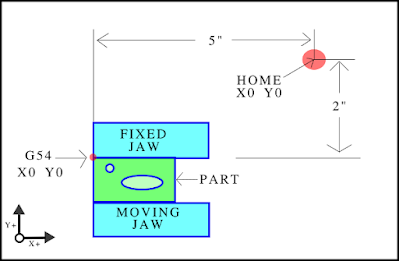
 Summing up so far there is MPos and WPos and a work envelope.  Next up an example.  Looking at the image to the left there is a part held in a vise.  The WPos is X-5 Y-2 and this G54 WPos is located at a corner of the fixed jaw.  The values of G54 have been stored in the control register.


On the left is a drawing of the part.  The drawing origin is the top left.


Here the work origin has been chosen in CAM software.  In CAM the work origin could be placed anywhere,  even some distance from the part.  In this case the logical X0 Y0 position matches the drawing origin.  The tri-color triad sits at the the work piece origin and the arrows point out the positive directions.


Referring back to the first image hopefully a logical pattern is apparent.  The fixed jaw never changes position so it's a good spot for Y0.  The left end of the vise matches the CAD/CAM X0.  Work holding is something to keep in mind at the CAD/CAM stage of making a part.

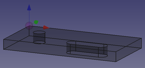
A very basic program for making the round hole with a tool of the same diameter:

G20  (move in inches)
G54  (Use G54 WPos)
G00 X0.25 Y-0.25  (A rapid XY move to the hole position)
S400 M03  (400 RPM clocwise if spindle isn't manual)
G00 Z0.2  (Rapid Z move to 0.2" above the part)
G01 Z-0.125 F50  (Feed to 0.125" depth at 50 ipm)
G00 Z0.2  (Rapid Z move to 0.2" above the part)
M02  (program finished)

The code above is the first time a Z WPos is mentioned.  The reason for this is Z WPos can be more complex than X or Y WPos.  On a machine not using tool length offsets the Z WPos is most commonly the distance the Z axis travels from HOME (MPos Z0) until the tool touches the top of the part.  For example if the machine is at HOME (MPos Z0) with a tool in the spindle and the machine Z axis is moved Z -3" before the tool touches the top of the part, the G54 Z WPos is -3".  Going back to the vise example G54 would be X -5, Y -2, Z -3.

Users coming from a 3D printer background may prefer to measure WPos Z0 from the bottom surface  of a part.  This is certainly possible if the CAM program was created with that in mind.  In my experience placing WPos Z0 at the top of a part is the convention and I'll offer 2 possible reasons why.

Reading the previous g-code it could be rewritten with WPos Z0 at the bottom of the part.  (The part is 0.125" thick)

G20  (move in inches)
G54  (Use G54 WPos)
G00 X0.25 Y-0.25  (A rapid XY move to the hole position)
S400 M03  (400 RPM clocwise if spindle isn't manual)
G00 Z0.325  (Rapid Z move to 0.2" above the part)
G01 Z0 F50  (Feed to 0.125" depth at 50 ipm)
G00 Z0.325  (Rapid Z move to 0.2" above the part)
M02  (program finished)

Only a small change, a bit messier to read but no problem.  Now create 7 holes spaced an inch apart with no 2 depths the same.


 First a program with WPos Z0 at the top of the part.  The part is 2" thick but knowing that isn't important to the program. The g-code below is only the Z plunge moves and  lateral and retract moves aren't shown.


G54
G01 Z-1.000 F50
Z-0.125
Z-0.500
Z-0.771
Z-0.994
Z-1.350
Z-0.846

Reads like a book.  Now the same plunge moves with WPos Z0 at the bottom of the part.

G54
G01 Z 1.000 F50
Z 0.750
Z 1.500
Z 1.229
Z 1.006
Z 0.650
z 1.154

Without using a calculator how deep is the tool plunging into the work?  If the part thickness was unknown what's the depth of the holes and can this code be reused on a thicker piece of material (without creating a fake WPos Z0).  Unlike a 3D printer milling is a subtractive process and code written to be subtractive is easier to read and write.

The image on the left represents a generic DRO as might appear on a cnc user interface.  Pressing the MPos will display the current distance from HOME position.  If the machine is at HOME these numbers should all read zero. With the MPos readout active, jog the machine to WPos X0,Y0,Z0 of the vise example, the numbers should read X -5.000 Y -2.000 Z -3.000.  If the machine is left in this position and the WPos button is pressed the DRO numbers will once again read zeros.  In addition the UI is likely to have a window scrolling the g-code lines as they are processed by the control.

Normally when running a program the DRO will be set to display WPos.  If the WPos Z0 is set to the top of the part it's easy to visualize the next Z move by looking at the displayed g-code.  When the tool is at the top of the part the DRO reads Z0.  If the next command is Z -0.5 it's obviously a move 0.5" below the top of the part.  If the WPos Z0 is the bottom of the part the depth of cut will be:          (thickness of part) - (commanded position)                                                              trying  to do that mental math gymnastics while a program is running is impractical and potentially dangerous.  Of course some users don't pay attention to the DRO and others have a DRO that displays distance-to-go.

I recommend using the part top as WPos Z0 unless there is a compelling reason to do otherwise.  For the reasons given and for a few other reasons that were not given.  If  the reasons supplied aren't convincing, look through some cnc text books or on-line tutorials provided by industry.  Examine how they explain set-up and programming to students and new users and some consistent approaches to work offsets will be noticed.  All of that said do whatever makes you comfortable and happy.  If you're reading a blog like this one cnc is unlikely to be the way you pay the bills.  And if the machine is all yours the 2nd shift won't leave a dead fish in your toolbox for having unconventional methods.                                                                     

 When running a machine for the first time the temptation will be to load a tool and start cutting.  A better plan is taking time to understand the machine and the g-code that commands the machine.  At the minimum know the commands G00 and G01. Start by getting the HOME position defined in the control and also define the travel limits.  After HOMING the machine, jog to the centre of the XY travel which should be at or near the centre of the table.  At this position set WPos to X0 Y0, this will be the G54 offset.  Make some XY motion using G00 and G01 commands in MDI mode.  Try positive moves and negative moves and diagonal moves.  At any time G00 X0 Y0 will return back to the centre.  To return to HOME try G53 G00 X0 Y0, G53 is a special command that moves in the MPos coordinate system.  When feeling confident with XY,  set the G54 Z0 and play with the Z moves.  Go through this exercise and the first time running a program will be less of a mystery.  Learn the machine and it will be fun instead of frustration.   


Wednesday 27 January 2021

From PDF to a Useful Part

 The gear example in this post came from a pdf intended for scroll saw users. This type of pdf can be opened directly in Inkscape.  The idea is the parts are printed on paper at full scale and the paper is then glued to a piece of wood.


 It's also possible to extract a drawing from a generic pdf using Inkscape's import via poppler option.  This wrench was extracted from a pdf repair manual.  The commands Ungroup, Path Break Apart and Path Combine were used to complete the task.  This trick could come in handy for transforming a logo to dxf or getting artwork for engraving.

This post is in part an expansion of a previous post:

https://steppingintocnc.blogspot.com/2021/01/freecad-dxf-problem-and-solution.html  


The pdf page on the left has some items that need to be removed as gear on the top right is all that's needed.  A sharp eye will notice a cleaner drawing exists on the bottom left so this isn't the best example.  Also Acrobat Reader has tools to simplify this task but open source tools do all that's needed.


In Inkscape turn off the page border in drawing preferences.  Left click and drag a selection box around the desired item.  From the Edit menu select invert selection and hit the delete key.  The page is now reduced to the image on the left.


 The image on the left shows all that is needed from the pdf page.  Reaching  this point can be a bit of a pixel hunt but drag-select can speed things up considerably.


Inkscape can export in dxf format but I've had some less than great experiences with that exporter.  QCAD has a very good svg importer so the drawing was saved as an Inkscape svg.  Inkscape by default is set to 90 dpi but if unsure check the application preference settings.

On the left is the svg imported in QCAD.  There are a huge number of segments so a decision will need to be made whether use as-is or recreate some of the geometry.  In this case the mess of segments in the centre were replaced with a true circle.  Before saving the dxf file make sure the drawing preferences are set to mm.


The next step is importing the dxf into FreeCAD.  It's also possible to import the svg file directly into FreeCAD but I find it easier to manipulate this type of file in QCAD.  I also have some reason to suspect the QCAD dxf is a more accurate representation of the original drawing compared to how FreeCAD interprets the svg.

From this point on the procedure is a rehash of the post mentioned at the top of this page.  And now a small note regarding the pocketing operation problems that prompted that post..............


    On this part I had best results by making the pocket the first operation and some grief doing this in any other order.  The vertical surface of the pocket is easily selected as the pocket geometry.  Good thing I got rid of all the segments eh ?

Monday 25 January 2021

Tool Length Offsets

 My newest toys for the cnc mill are Tormach tool holders.  Using these tool holders makes tool lengths repeatable unlike a standard R8 holder. Now tool changes are possible in the program instead of using 1 program per tool.  Linuxcnc with Axis UI is used but the interface shouldn't matter as the commands are in MDI.

X and Y offsets are fairly straight forward because they are based on the vertical centre of the spindle which does not change with tool length or diameter.  The Z offset changes every time a tool of different length is used.  The machine needs to adapt it's Z movements to accommodate tools of varying lengths and it does this using tool length offsets or TLO in short.


Tormach holders compress against the face of the spindle.  The distance from that contact point to the tip of the tool equals the total length of the tool.

tool + holder = TLO


I've chosen a method of TLO that results in all offsets being positive because they describe the true length of the tool.  My method is far from the only way and there are certainly more automated approaches.  It's old school and a variation on how tool are measured offline with a setting fixture and height gauge. The link below provides a good explanation of the pros and cons of positive TLO:

https://www.cnccookbook.com/touch-off-tool-setter-measuring-tools-for-length/

as the man says positive offsets demand caution.


 The image to the left shows the spindle face touching a block that is reserved for this purpose.  This is the position where G54 is set to zero.

btw the machine isn't out of tram,  the photographer has no skills. 


--> In MDI enter T0 M6 and also a G49 for an added bit of safety.

--> Lower the spindle face until it touches the top of the measuring block.

--> Set the current position to G54 Z0 using a touch-off button in the UI or entering G10 L20 P1 Z0 in MDI.

--> Set the DRO to read relative position.  It should now be reading Z0.

--> Place T01 in the spindle and move the tool tip to the top of the setting block.  The DRO will now display the distance from the tool tip to the spindle face. The DRO is being used as a poor man's height gauge.

--> Enter the displayed DRO Z value directly in the tool table (not recommended) or in MDI enter T01 M6 and G10 L10 P1 Z0

-->Place T02 in in the spindle and move the tool tip to the top of the setting block.

-->In MDI enter T02 M6 and G10 L10 P2 Z0.  Notice that P represents the tool #

Continue that pattern for any additional tools. MDI displays a command history so the commands don't need to be memorized.  Below is a small test program for 3 tools:

#######################################

(move block somewhere other than directly under tool)
g90
g20
g54
g53 g0 z0
(if G53 crashes it's time to rethink the machine's basic setup)
T1 M6
G54
g0 x0 y0
g43 z2 h01
g01 z.1 f50
z0 f20
m0
(slide block under tool to check)
(remove block and resume program)
g01 z0.1
g53 g0 z0
t2 m6
g49
g00 x0 y0
g43 z2 h02
g01 z.1 f50
z0 f20
m0
(slide tool under tool to check)
(remove block and resume program)
g01 z.1
G53 g0 Z0
t3 m6
g49
g00 x0 y0
g43 z2 h03
g01 z.1 f50
z0 f20
m0
(slide block under tool to check)
(remove block and resume program)
g01 z0.1
g53 g0 z0
m2

###############################

If all has gone to plan running this program should result in each tool travelling to the top of the setting block, no more and no less.  So why use positive TLO instead of the more common method used in the hobby world ?  Place a different height of block on the table.  Now load any of the already measured tools in the spindle taking care that the correct TLO is active.  Move the tool tip to the top of the new surface and set G54 to Z0.  If the test program is run again all tools should stop at this new Z height.  Cool trick but I don't recommend setting G54 this way.  Instead set G54 using the spindle face.

--> in MDI enter T0 M6 and G49

--> Now move the spindle face to the top of the new block (or work piece).  Now set G54 to Z0 and rerun the test program (or another program).  The TLO when set as outlined above are portable to any work piece, only fixture offsets need to be changed.

If tools start crashing I'll return to edit this post but no crash is expected due to the methods.  However human error is expected and in my case guaranteed.

An above average youtube video that relates to this topic:


Wednesday 20 January 2021

FreeCAD: A DXF Problem and a Solution

 DXF isn't FreeCAD's native format but sometimes it's the file format you're given.  I'm starting a new clock build and dxf is what the designer supplied.

QCAD is diplaying a huge number of segments.  The first temptation is to completely reconstruct the drawing into something sensible but maybe FreeCAD can deal with it as-is ?


The dxf is imported into FreeCAD's Draft Workbench.

Edit -> Select All

Modification -> Draft to Sketch

When transformation to sketch is complete hit delete on the keyboard to get rid of all the imported shapes.


In the Sketcher Workbench:

Sketch -> Validate Sketch

Use the resulting dialogue box to examine the sketch for errors.  In this case 1244 missing coincidences were found.  Click fix to repair.  No other errors were found.


In Part Design Workbench select Create a Body from the toolbar.  Right click the sketch in tree view and select move object to other body.  Pad the sketch to desired thickness.


In Path Workbench create job object as usual.  Now comes the part that wasn't working for me until a user  posted a solution in the FreeCAD forums.

https://forum.freecadweb.org/viewtopic.php?f=15&t=54540
 

Do not try a pocket operation on this part.  Choose a profile operation and select the bottom face as the  base geometry.  In the operation options select: Outside,  Holes,  Circles, Perimeter,  Compensation.


 Another possibility is adding a bottom surface and choosing that surface for pocketing.  The downside is a longer calculation time and really there's nothing gained from grinding up the excess material


FreeCAD also has a Legacy dxf importer that apparently works better in some cases.  There's also many settings available in Preferences.  My options are all set to whatever defaults come with the FreeCAD.  Units can be a source of confusion with dxf files and I find good 2D CAD software is the best place to deal with such things and anything dxf really.  My longtime go-to is QCAD.  


Tuesday 19 January 2021

Arc-fitting and Arc-breaking with bCNC

 How does CAM deal with constant radius arcs and near-arcs ?  Fusion 360 has smoothing and tolerance settings in the general operation (pre-post process) dialogue box which determines how splines are treated in terms of tangent arcs or line segments. The actual post process may make additional changes.  It will attempt to do arc-fitting if told to do so.  FreeCAD doesn't have an exact equivalent to the best of my knowledge.  It does have a user settable geometry tolerance setting but I haven't found any documentation that describes what this does in any detail.  It does do some arc-fitting as will be described further down this page.  True arcs are output as G2/G3 in both Fusion and FreeCAD although Fusion 360 includes at least one post process that posts all arcs as line segments.

This topic was prompted by a couple of things.  First was an earlier post about nesting and discovering Deepnest can do bad things to arcs.  Second was seeing the elimination of G2/G3 as a recurring topic on the FreeCAD forums.

Among the many interesting things bCNC can do with existing g-code are the tools Linearize and ArcFit.  Arc fitting will attempt to replace a series of line segments that approximate an arc with G2/G3 arcs.  Linearize does the opposite, replacing G2/G3 arcs with line segments.

The image to the left is the QCAD property editor looking at a dxf exported from Deepnest.  A 50mm circle has a circumference of 157mm and with a 0.050mm curve tolerance set in Deepnest there are only 144 segments ? Curve Tolerance doesn't work exactly as I expected.  No problem as this dxf resulted in FreeCAD posting G2/G3 arcs.  It appears FreeCAD does arc-fitting even if the setting is not visible to the user.

Click on any image to enlarge


In another case Deepnest has broken a 38.1mm circle into 40 segments.  FreeCAD's g-code output has refined the arc by increasing the number of segments to 74.  No G2/G3 arcs were produced.  The tool used was 6.35 diameter.

Using the settings seen on the left bCNC replaced the 74 line segments with 6 arcs.  The maximum deviation from the true diameter was 0.03mm compared to the 0.17mm deviation found in the original FreeCAD output.  Setting a finer arc precision in bCNC creates more arcs and may reduce deviation even more.  My testing didn't explore this further.


  The image on the left is the bCNC editor displaying the results of arc fitting.  This 12 line block will replace the 77 line block created by FreeCad.  The 77 line block is listed directly above the expanded 12 line block.


Below is the exported file from bCNC is 21 lines replacing the original 105 line FreeCAD file.  Somehow the 5mm Z cut depth was lost,  possibly due to user error.

G17 G54 G40 G49 G80 G90
G21
G54
M5
M6 T1
G43 H1
M3 S0
G0 Z5.000
G0 Z3
G0 X15.705 Y15.705
G0 Z0
G2 X20.584 Y8.357 I-15.222568 J-15.40144 Z0 F400
G2 X21.695 Y-4.781 I-21.577207 J-8.440627 Z0
G2 X-1.383 Y-22.197 I-21.894967 J5.014727 Z0
G2 X-22.197 Y1.382 I1.67678 J22.456271 Z0
G2 X8.931 Y20.344 I22.263697 J-1.517216 Z0
G2 X15.705 Y15.705 I-8.605303 J-19.831003 Z0
G0 Z3
M05
G17 G54 G90 G80 G40
M2


On the left is FreeCAD g-code displayed in the bCNC editor.  The next block in the editor is the output of Linearize which broke the G2/G3 arcs into many straight segments.  Notice the block of linearized g-code is 1045 lines.  Click to enlarge the image.


   The image on the left shows the settings that created the large number of straight segments.


Linearize could be useful foe Easel users or others unable to use G2/G3 in the g-code.  ArcFit could be more universally useful.  For example g-code created using  files made in Inkscape from photo or pdf  are possible candidates.